
Kawboy's restoration/conversion of a 1980 KZ13
- biltonjim
-

- Offline
- Platinum Member
-

- Posts: 972
- Thanks: 250
Re: Kawboy's restoration/conversion of a 1980 KZ13
11 years 1 day ago
Great job. This is a modification I shall keep in mind, if I ever get to restoring my KZ.
Interesting to see the TIG welds. It looks as though the heat does not have chance to spread far through the metal. I only have experience with Oxy / Acetylene welding and brazing, but I think I will look into buying a TIG machine.
Interesting to see the TIG welds. It looks as though the heat does not have chance to spread far through the metal. I only have experience with Oxy / Acetylene welding and brazing, but I think I will look into buying a TIG machine.
Please Log in or Create an account to join the conversation.
- Kawboy
-
Topic Author
- Offline
- Sustaining Member
-

- Posts: 3250
- Thanks: 1203
Re: Kawboy's restoration/conversion of a 1980 KZ13
10 years 10 months ago
Well the cam chain tool came in so it was time to have at it. When I removed the chain I tied a piece of string onto the end of the old chain and then pulled the chain out. So now I had the string in place to help install the new chain. Tied the end of the string on to the new chain and fed it in to the engine and around the shaft. Interesting point was when I was removing the old chain I couldn't get it to disengage from the gear down below so I had to rotate the engine and feed it off of the gear. When I went to put it back in the chain ran around the shaft but not on the gear and I thought what are the chances that if I rivet it all back up, I won't be able to get the chain back on to the drive gear on the secondary shaft. Better check first. Sure enough with a bit of maneuvering it went back up on to the gear. So keep that in mind when you're dropping the cam chain to do other work like removing the head.
Anyway, the chain breaking riveting tool doesn't work very well when you try to split the chain. It's a shitty design when using on small chain, so I was forced to grind the pins enough to remove the side link from the chain. And a word to the wise, if you're going to try to do this job, beware, when you remove the side link and then remove the master link, there are 3 intermediate links that will drop out.
So now all I have to do is remove the string and install the master link. Now that's fun. That chain wants to pull itself into the crankcase. I have hands the size of bear paws. Try holding 2 ends of the chain and inserting the master link and lining up 4 intermediate links from both chain ends and at the same time inserting 3 intermediate links while pushing the master link through the 2 chain ends. Took a few minutes and I didn't drop anything thank God. Now you have to put the end link on the master link. Well, it's a .004" interference fit between the holes on the side link and the pins on the master link, so in essence you have to press the plate on to the pins on the master link, but not too far or the chain will bind on itself. I found enough pieces in the chain riveting tool to put together to get it done but as you press the link on you need to check the fit with a Vernier. So a little bit at a time and check, check, check. Got the side plate to within .002" of the final size. Now time to flare the end of the master link. Again, found the pieces in the riveting tool and assembled but this tool is more designed for larger chains like 530 drive chains. In the end got it set up and started pressing. Took my time and kept measuring with the Vernier. Probably pressed each pin about 5-7 times and checking as I went. End result, the master link ended up .002" narrower than the rest of the chain and the link is free and not binding, so I'm really happy with the result.
Another thing If I were to do this job again, I would order an extra couple of master links. If you over press the pins on the link, the chain could bind and that's not good, so if you had to, you could just grind off the master link and do it over again. I made the mistake of not getting an extra, so I was really careful not to over press the pins.
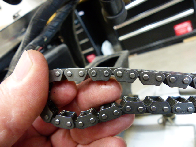
Hope you can see the master with the different flare on the end of the pins. One pin didn't flare quite in the center of the pin, the other looks really good, but I'm not worried since there's no movement between the outer link and the pin, only between the pin and the inner links. Time to start reassembly. Yippee!!!
Anyway, the chain breaking riveting tool doesn't work very well when you try to split the chain. It's a shitty design when using on small chain, so I was forced to grind the pins enough to remove the side link from the chain. And a word to the wise, if you're going to try to do this job, beware, when you remove the side link and then remove the master link, there are 3 intermediate links that will drop out.
So now all I have to do is remove the string and install the master link. Now that's fun. That chain wants to pull itself into the crankcase. I have hands the size of bear paws. Try holding 2 ends of the chain and inserting the master link and lining up 4 intermediate links from both chain ends and at the same time inserting 3 intermediate links while pushing the master link through the 2 chain ends. Took a few minutes and I didn't drop anything thank God. Now you have to put the end link on the master link. Well, it's a .004" interference fit between the holes on the side link and the pins on the master link, so in essence you have to press the plate on to the pins on the master link, but not too far or the chain will bind on itself. I found enough pieces in the chain riveting tool to put together to get it done but as you press the link on you need to check the fit with a Vernier. So a little bit at a time and check, check, check. Got the side plate to within .002" of the final size. Now time to flare the end of the master link. Again, found the pieces in the riveting tool and assembled but this tool is more designed for larger chains like 530 drive chains. In the end got it set up and started pressing. Took my time and kept measuring with the Vernier. Probably pressed each pin about 5-7 times and checking as I went. End result, the master link ended up .002" narrower than the rest of the chain and the link is free and not binding, so I'm really happy with the result.
Another thing If I were to do this job again, I would order an extra couple of master links. If you over press the pins on the link, the chain could bind and that's not good, so if you had to, you could just grind off the master link and do it over again. I made the mistake of not getting an extra, so I was really careful not to over press the pins.
Hope you can see the master with the different flare on the end of the pins. One pin didn't flare quite in the center of the pin, the other looks really good, but I'm not worried since there's no movement between the outer link and the pin, only between the pin and the inner links. Time to start reassembly. Yippee!!!
Please Log in or Create an account to join the conversation.
- aus_z1300
-
- Offline
- Elite Member
-

- Posts: 176
- Thanks: 21
Re: Kawboy's restoration/conversion of a 1980 KZ13
10 years 10 months ago
Do you have pics of the tool you used .I am considering one from ebay to do a cam chain on a ktm. I have read that a few people have modified the bit that does the damage to make the pressed ends look like the originals.
Please Log in or Create an account to join the conversation.
- Kawboy
-
Topic Author
- Offline
- Sustaining Member
-
- Posts: 3250
- Thanks: 1203
Re: Kawboy's restoration/conversion of a 1980 KZ13
10 years 10 months agoThis is the one I picked up off of EBay. $23.99 + $9.00 shipping. You can follow the link in the EBay ad to a YouTube video on how it works but to tell the truth, some of the pieces just don't fit the really small cam chain. The best way to do this job is grind off the rivet heads on one side plate and pry off the side plate. Then pull out the master link and catch the intermediate pieces. When putting the new side plate on, it requires you to press it on because of the interference fit between the pins and the side plate. I found the riveting rear anvil and the front guide for pressing out the pin to work quite well for pressing on the side plate. The only issue is you're working on one pin at a time so your walking the side plate into place instead of pressing it on in parallel.
The finished rivet head looks just like any other rivet head I've seen on drive chains and the flare on the head is only to displace the metal enough to stop it from coming out of the side plate. I wouldn't mess around with modifying the rivet anvil. I don't think it's necessary.
The following user(s) said Thank You: aus_z1300
Please Log in or Create an account to join the conversation.
- Kawboy
-
Topic Author
- Offline
- Sustaining Member
-
- Posts: 3250
- Thanks: 1203
Re: Kawboy's restoration/conversion of a 1980 KZ13
10 years 8 months ago
It's been a while since I posted any updates on my own restoration, so he goes.
I started working on this engine almost 20 years ago and at that time I had cleaned up the ports in the head and ground the valves and valve seats. I remember having to rush and get it back together because we (the wife and I) were moving house. Didn't get a chance to verify the valve fits at that time. Now 20 years later it's time to make this bike righteous. I decided to pull the head off and get my head wrapped around where I had left off and I'm glad I did. Strangely enough I found a bent valve and a couple of valves where the margins on the valves were less than acceptable. There's a wealth of information in the service manual and now that I'm older and more wise, I now take the time to verify everything against the standards, which in this case IS THE INFORMATION IN THE MANUAL!!!
One thing I found very interesting was after I pulled the valves out I happened to look at the valve seals and they appeared to be oval. That's strange since they were new when I put the head together 20 years ago, so what's going on? I squeezed the seal and it kept the shape so the seals had gone hard just from sitting. The engine was never run. The seals were never heated up and yet they had gone hard. Usually you can write off rubber items when they are exposed to UV rays but this was not the case here, so I have no explanation.
The head has been sent to the machine shop to have the valve seats recut and the valves licked to make sure they're cut properly and the valves which didn't meet the margin spec will be replaced with spare valves from a spare head.
In the meantime I've been fairing out the ducktail mod to the tailpiece. It's coming along nicely. Can't wait to see what this will look like once it's painted. I also found a site which had the paint mixture for the Candy Glory Red paint which is the Honda CBX color and got the tint sent up from Alsa paints in California. How lucky we are to be able to converse on the internet and find suppliers anywhere in the world and buy products we want.
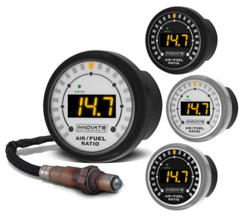
I'm a bit of a techy if you've not figured it out by now. That being said, I've decided to install a wideband O2 air fuel monitor on this bike. This will be the ultimate in dialing in the carb jetting and main jet needle position. it will also give me a chance to see how different fuels and different weather conditions play a part in the jetting selected. It will be very interesting to see what I end up with for jetting compared to all of the jetting selections I've seen posted on this site. Stay tuned (no pun intended) for the results of this aspect of my build.
Here's the wideband O2 set up on it's way from EBay
I started working on this engine almost 20 years ago and at that time I had cleaned up the ports in the head and ground the valves and valve seats. I remember having to rush and get it back together because we (the wife and I) were moving house. Didn't get a chance to verify the valve fits at that time. Now 20 years later it's time to make this bike righteous. I decided to pull the head off and get my head wrapped around where I had left off and I'm glad I did. Strangely enough I found a bent valve and a couple of valves where the margins on the valves were less than acceptable. There's a wealth of information in the service manual and now that I'm older and more wise, I now take the time to verify everything against the standards, which in this case IS THE INFORMATION IN THE MANUAL!!!
One thing I found very interesting was after I pulled the valves out I happened to look at the valve seals and they appeared to be oval. That's strange since they were new when I put the head together 20 years ago, so what's going on? I squeezed the seal and it kept the shape so the seals had gone hard just from sitting. The engine was never run. The seals were never heated up and yet they had gone hard. Usually you can write off rubber items when they are exposed to UV rays but this was not the case here, so I have no explanation.
The head has been sent to the machine shop to have the valve seats recut and the valves licked to make sure they're cut properly and the valves which didn't meet the margin spec will be replaced with spare valves from a spare head.
In the meantime I've been fairing out the ducktail mod to the tailpiece. It's coming along nicely. Can't wait to see what this will look like once it's painted. I also found a site which had the paint mixture for the Candy Glory Red paint which is the Honda CBX color and got the tint sent up from Alsa paints in California. How lucky we are to be able to converse on the internet and find suppliers anywhere in the world and buy products we want.
I'm a bit of a techy if you've not figured it out by now. That being said, I've decided to install a wideband O2 air fuel monitor on this bike. This will be the ultimate in dialing in the carb jetting and main jet needle position. it will also give me a chance to see how different fuels and different weather conditions play a part in the jetting selected. It will be very interesting to see what I end up with for jetting compared to all of the jetting selections I've seen posted on this site. Stay tuned (no pun intended) for the results of this aspect of my build.
Here's the wideband O2 set up on it's way from EBay
Please Log in or Create an account to join the conversation.
- Kawboy
-
Topic Author
- Offline
- Sustaining Member
-
- Posts: 3250
- Thanks: 1203
Re: Kawboy's restoration/conversion of a 1980 KZ13
10 years 8 months ago
Had an interesting day today. Went to the big city and picked up my new O2 wideband air fuel gauge. Can't wait to see how nice this is to work with when dialing in the carbs.
I've also decided to have the camshafts ground so off to a machine shop to find out what cost and what grind I could get. The shop I went to has 600 cam profiles that he can grind to so he will be checking his masters and tell me what he can grind. I'm hoping for around 285- 290 deg. duration and around .340- .360" lift. The head is mildly ported (mostly cleaned up the bowls and removed the burrs in the ports) and believe me, there's lots of material in the port bowls that need work to smooth them out. The machinist looked at the cams and noted that there was some significant wear on several of the cam lobes and when he said it, I thought he was shining me on since the 65 year old guy didn't have his glasses on. All he had to do was run his finger over the nose of the cam and he could feel the flat spot on the toe on the side of the flank. He showed me what he was talking about and I could feel it as well. So I learned something today about checking cams. The lobed looked good but just by feeling them you could tell they were worn. I now wished that I had taken a pic of the cams before leaving them. Long story short, if he has a master in the range I'm looking for, it will cost $110.00 per camshaft to regrind. If he has to make a master, then it will cost an additional $240.00 to cover the cost of the master. All in all, that's not a bad price to do this work. Megacycle cams wanted $800.00 to do the same. Mind you Megacycle was going to build up the lobes and leave the base circle alone to accomplish this where in this case, we are going to regrind the existing lobes and accommodate the difference by cutting the valve seats and grinding the valve faces which will set the valves a little deeper in the head then shim accordingly. Some fancy fitting going on here and I know what has to be done. Just have to give clear direction to the people doing the work. If I had access to the equipment needed to do this work, I'd do it myself. if I ever win the Lotto, I'm going to set up a auto machine shop for machining engine parts since this is what Heaven is to me. Can you tell I'm a motor head??
I've also decided to have the camshafts ground so off to a machine shop to find out what cost and what grind I could get. The shop I went to has 600 cam profiles that he can grind to so he will be checking his masters and tell me what he can grind. I'm hoping for around 285- 290 deg. duration and around .340- .360" lift. The head is mildly ported (mostly cleaned up the bowls and removed the burrs in the ports) and believe me, there's lots of material in the port bowls that need work to smooth them out. The machinist looked at the cams and noted that there was some significant wear on several of the cam lobes and when he said it, I thought he was shining me on since the 65 year old guy didn't have his glasses on. All he had to do was run his finger over the nose of the cam and he could feel the flat spot on the toe on the side of the flank. He showed me what he was talking about and I could feel it as well. So I learned something today about checking cams. The lobed looked good but just by feeling them you could tell they were worn. I now wished that I had taken a pic of the cams before leaving them. Long story short, if he has a master in the range I'm looking for, it will cost $110.00 per camshaft to regrind. If he has to make a master, then it will cost an additional $240.00 to cover the cost of the master. All in all, that's not a bad price to do this work. Megacycle cams wanted $800.00 to do the same. Mind you Megacycle was going to build up the lobes and leave the base circle alone to accomplish this where in this case, we are going to regrind the existing lobes and accommodate the difference by cutting the valve seats and grinding the valve faces which will set the valves a little deeper in the head then shim accordingly. Some fancy fitting going on here and I know what has to be done. Just have to give clear direction to the people doing the work. If I had access to the equipment needed to do this work, I'd do it myself. if I ever win the Lotto, I'm going to set up a auto machine shop for machining engine parts since this is what Heaven is to me. Can you tell I'm a motor head??
Please Log in or Create an account to join the conversation.
Moderators: dcarver220b
Time to create page: 0.198 seconds