
Aftermarket piston rings
- McBoney
-

- Offline
- Platinum Member
-

- Posts: 561
- Thanks: 87
Re: Aftermarket piston rings
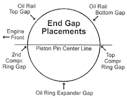
7 years 5 months agoKawboy wrote: The ring ends should never be located on the thrust sides (front and rear) of the piston.
The manual on page 75 says the opening in the top ring and the oil expander should be facing forward, and the opening of the second ring should be facing backwards ...
What have I missed?
Paul
Six-Pot-Cafe in the making...
Please Log in or Create an account to join the conversation.
- Kawboy
-

- Offline
- Sustaining Member
-

- Posts: 3212
- Thanks: 1177
Re: Aftermarket piston rings
7 years 5 months ago - 7 years 5 months agoMcBoney wrote:Kawboy wrote: The ring ends should never be located on the thrust sides (front and rear) of the piston.
The manual on page 75 says the opening in the top ring and the oil expander should be facing forward, and the opening of the second ring should be facing backwards ...
What have I missed?
Paul
Good question. Better still what did Kawasaki miss?
Since the inception of the mighty KZ1300, this engine has had a known oil consumption problem. The only 2 places where oil can be consumed as opposed to leaked is the piston ring to cylinder wall seal and the intake valves to valve stem seal. It's more than likely a problem with the piston ring to cylinder wall seal. Valve stem to valve guide clearances are in the neighborhood of .0004" - .0007" on a diameter of 7mm. Not a lot of space in their for oil to go through although with a differential pressure of anything from 8" HG - 28" hg vacuum will enhance that clearance.
Sometime in the 1980-1981 Kawasaki came out with a service bulletin calling for cylinder honing and piston ring replacement but as I understand it, it wasn't the "Holy Grail" to fixing the problem. It did make a significant difference. The engineering background in me question the early failure of the piston ring seal. A good rule of thumb for piston ring wear/ replacement change out is usually 75,000-100,000 kilometers unless the engine is being run at moderate to full load for most of its life and then you can cut that number down by 1/2 or more. This is where I look to a leak down test to make my determinations.
So back to your question. Since the mid 1960's, Kawasaki has been in the business of manufacturing motorcycles as a 5% of their total Kawasaki Heavy Industries business. They weren't new to the game. The question then is how and for what reason did they have a known oil consumption problem with the KZ1300? Machining practices would have been the same as other models. Piston and piston rings would have met similar standards to other models. So what went wrong?
This is where the engineering side of me looks in other places for similar practices and compare the practices to see if I can find fault with the failed practice. So off I go on a search for information. Where does one look? Other service manuals would be nice but one has to pay for that information. Aftermarket piston and piston ring suppliers supply installation information for their products because not everybody who rebuilds engines actually follow service manuals and to minimize failure of the product they just sold you, they supply information to guide you so you have good success and then in turn, tell "All of your buddies" about replacing your *** with this fantastic new product.
I also CONSIDER tribal knowledge. Nothing like hearing stories from Master Engine Builders about how they have overcome common problems and adopted new practices across the board to alleviate those common problems. My inquiries led me several piston ring manufacturers/suppliers and also piston manufacturers/suppliers and the guidelines for installation vary widely. Most want you to locate the top ring and second ring on 45 degrees to the center line and facing forward. The thrust face being the backside of the cylinder when considering the rotation of the engine since the piston is levering itself off of this cylinder face. That places the top ring and second ring end gaps on the minor thrust face i.e. when the piston is on compression since the crankshaft and connecting rod is trying to push the piston into that cylinder wall. The forces on top of the piston on compression 100-150 psi where the piston pressure after ignition can be as high as 400 psi. Hope that explains the minor thrust face (the front side of the cylinder) and the major thrust face (the backside of the cylinder)
There are other piston ring suppliers such as Wiseco and Hastings who want the top and second ring end gaps located on the piston pin center line opposite each other. No explanation for this but definitely a completely different perspective from their rivals. So why would you follow them when they contradict their competition?
Now I bring up the tribal knowledge. I know several Master Engine Builders. A few of them just build engines for the domestic market. Nothing fancy here. I also know Race engine builders who build sprint car engines, dragster engines running NOS, turbos etc. These guys are more interested in the engineering aspects and when challenged with a problem like oil consumption, would go back to their suppliers for answers. After all, their business is fundamentally based on building the best of the best.
The ring manufacturers believe that a lot of action happens on the major and minor thrust faces due to piston rocking/rattling in the bore and they collectively seem to agree that presenting a solid ring face on those thrust faces has less flutter effect of the ring in the ring groove lands. Less flutter helps maintain the seal between the piston rings, the piston ring groove lands and the cylinder walls minimizing pressure losses from combustion and helping the control of the engine oil.
I tend to look at all of the information presented to me and wade through it all and come up with my own conclusions. Then I put that information into practice and monitor for change. That's what an engineer would do. When you are presented with information like "ring flutter" you start to pay attention and listen. If you accept ring flutter as a probable condition, then you would want to minimize that effect. Where could you locate the ring ends to minimize that effect? If piston rocking magnifies the effect, where on the piston is there minimal movement during the rocking? Answer, along the wrist pin center line. So let's place the weakest points of the rings on the center line of the wrist pins and that places the most solid portion of the piston rings on the major and minor thrust faces. Golly be!!
The oil control rings are another story. They are designed to scrape off excess oil from the cylinder walls and direct that excess hot oil through the oil control holes in the piston but at the same time, must leave a film of oil on the walls to act as a cushion between the piston, piston rings and the cylinder. If you had to sacrifice a sealing point of the rings due to ring end gaps, where would you want the excess oil left. On the major thrust face for cushioning and lubrication so why don’t we leave the open ring gaps facing the backside of the engine. The only consideration here is the middle oil control ring. It’s fragile due to its wavy shape and needs to be controlled as well. So if we face the open gap of the middle control ring towards the minor thrust face and stagger the oil control upper and lower rings on the major thrust face but locate the gaps 90 degrees to each other, then we have a solid oil control ring package, nice and solid, minimizing ring flutter and leaking oil on the major and minor thrust faces.
After considering this information I have adopted this ring clocking practice for 4 stroke engines and had great success. It’s a total package. Precision honing, good quality rings and following the diagram.
Last edit: 7 years 5 months ago by Kawboy.
The following user(s) said Thank You: McBoney
Please Log in or Create an account to join the conversation.
- McBoney
-
- Offline
- Platinum Member
-
- Posts: 561
- Thanks: 87
Re: Aftermarket piston rings
7 years 5 months ago - 7 years 4 months ago
I would lnever have thought of it like this, but as explained, it makes perfect sense.
One thing.... and I may have read it wrong in which case my apologies, but I think your text is at odds with the picture... I think the front of the engine in the picture is 'north'... not as shown 'west'... or have I mis-read?
Paul
One thing.... and I may have read it wrong in which case my apologies, but I think your text is at odds with the picture... I think the front of the engine in the picture is 'north'... not as shown 'west'... or have I mis-read?
Paul
Six-Pot-Cafe in the making...
Last edit: 7 years 4 months ago by Kawboy.
Please Log in or Create an account to join the conversation.
- Kawboy
-
- Offline
- Sustaining Member
-
- Posts: 3212
- Thanks: 1177
Re: Aftermarket piston rings
7 years 4 months ago - 7 years 4 months agoMcBoney wrote: I would lnever have thought of it like this, but as explained, it makes perfect sense.
One thing.... and I may have read it wrong in which case my apologies, but I think your text is at odds with the picture... I think the front of the engine in the picture is 'north'... not as shown 'west'... or have I mis-read?
Paul
I copied that picture from www.wiseco.com/PDFs/Manuals/RingEndGap.pdf website and I believe the picture is referring to a North American V8 engine in which case the crankshaft turns clockwise. The major thrust would be at the top of the picture and the minor thrust would be at the bottom of the pic. If we used the pic for reference to our KZ engines, the front of the engine as pictured, would be the right side of the KZ engine.
And for the record now that I've provided the Wiseco information on how to fit and install the rings, I will state the I NEVER , NEVER, EVER install rings with a ring expansion tool. You take a chance of stressing the ring and yielding the material which can distort the ring and make it out of round. I've always followed the practice of walking the rings on to the pistons. This I learned the hard way when I got caught using my 2 index fingers and 2 thumb nails to expand the ring to slip it over the piston only to be cuffed over the back of the head by an instructor at trade school. When I came to, he then proceeded to show me the right way to do it. Walking on the rings is so easy on the rings you can feel how stress free it is.
Last edit: 7 years 4 months ago by Kawboy.
Please Log in or Create an account to join the conversation.
- McBoney
-
- Offline
- Platinum Member
-
- Posts: 561
- Thanks: 87
Re: Aftermarket piston rings
7 years 4 months ago
Got it. The front of the KZ engine is 'south' in the diagram.
Thank you!
Paul
Thank you!
Paul
Six-Pot-Cafe in the making...
Please Log in or Create an account to join the conversation.
- Bucko
-
- Offline
- Platinum Member
-
- Posts: 660
- Thanks: 165
Re: Aftermarket piston rings
7 years 4 months ago - 7 years 4 months agoKawboy wrote: …..Since the mid 1960's, Kawasaki has been in the business of manufacturing motorcycles as a 5% of their total Kawasaki Heavy Industries business. They weren't new to the game. The question then is how and for what reason did they have a known oil consumption problem with the KZ1300? Machining practices would have been the same as other models. Piston and piston rings would have met similar standards to other models. So what went wrong?
My theory is that this was the largest motorcycle engine they had built, their first six, and their first motorcycle engine that was water cooled – i.e. I don’t think they knew what they were doing.
If remember correctly (and I often don’t) later KZ1300 pistons had more oil return holes drilled in the oil ring lands.
Hello from Canada's We(s)t coast.
Last edit: 7 years 4 months ago by Bucko.
Please Log in or Create an account to join the conversation.
Moderators: scotch
Time to create page: 0.176 seconds