
Electrical
M-Unit Blue wiring
- scotch
-

- Offline
- Sustaining Member
-

- Posts: 1996
- Thanks: 904
Re: M-Unit Blue wiring
5 years 10 months ago
kawboy ! You must have had AC/DC on the radio when you were responding ! :woohoo: Honest mistake.
Glad it wasn't ABBA. That would have been confusing ! :whistle:
Glad it wasn't ABBA. That would have been confusing ! :whistle:
1980 KZ 1300 sr# KZT30A-009997
Always High - Know Fear !
Always High - Know Fear !
Please Log in or Create an account to join the conversation.
- McBoney
-
 Topic Author
- Offline
- Platinum Member
-

- Posts: 561
- Thanks: 87
Re: M-Unit Blue wiring
5 years 10 months ago
Battery box is a bust. I need to start over as my handywork is appalling.
Anyway, I did a diagram and think I have sussed the wiring. But I’ll do a proper diagram later. And this is just the charging and ignition section.
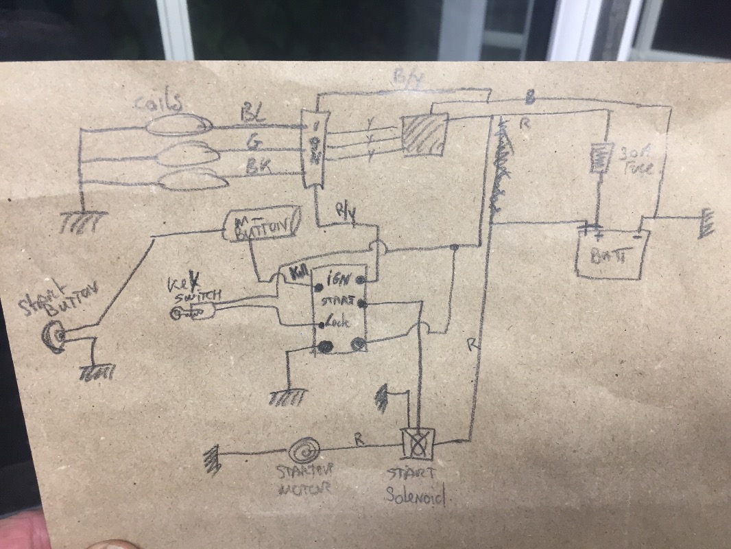
Anyway, I did a diagram and think I have sussed the wiring. But I’ll do a proper diagram later. And this is just the charging and ignition section.
Six-Pot-Cafe in the making...
Please Log in or Create an account to join the conversation.
- englishcw
-

- Offline
- Senior Member
-

- Posts: 44
- Thanks: 21
Re: M-Unit Blue wiring
5 years 10 months ago - 5 years 10 months ago
Hi Paul , I fitted a 30 Amp Fuse , because I had one handy . Then reading the instructions again it said '' 40 Amp maximum '' , and also showed a 40 Amp in the diagram , so I erred on safety , and purchased a 40 Amp Fuse . 2 for about £9 , ebay , and they have little fixing holes .
Last edit: 5 years 10 months ago by englishcw.
The following user(s) said Thank You: McBoney
Please Log in or Create an account to join the conversation.
- McBoney
-
Topic Author
- Offline
- Platinum Member
-
- Posts: 561
- Thanks: 87
Re: M-Unit Blue wiring
5 years 10 months ago - 5 years 10 months ago
Hi again,
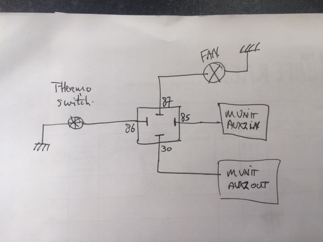
I have started wiring in and I have hit a mental block. May I please ask you to have a look at the attached diagram to see if that is done correctly?
This is for the fan with the switch on the left and the solenoid in the middle. I will deal with the 1 minute delay factor when it is running as that acc to the manual can be programmed in to the M Unit Aux 2.
Cheers
Paul
Six-Pot-Cafe in the making...
Last edit: 5 years 10 months ago by McBoney.
Please Log in or Create an account to join the conversation.
- tackelhappy
-
- Offline
- Platinum Member
-
- Posts: 409
- Thanks: 163
Re: M-Unit Blue wiring
5 years 10 months ago - 5 years 10 months ago
I'm not sure how the oem fan relay works, because I didn't have one to begin with and I also find it easier to use a manual switch. I have an accurate digital temp. gauge and turn the fan on and off around 95 centigrade. My system also allowed me to test it before the engine was running -simple on/off from the handlebar.
Your diagram should work providing the inputs/outputs from the relay are in the right place. And without a running engine, how do you check.
Another question would be - how will you know, when the fan switch is trying to prompt the fan to come on, without connecting it directly to the m-unit in. Your plan requires the power to go through the relay.
Maybe you could put 12volts to the fan switch-red/white wire and see what happens. Just remember there is no fuse in place if this idea is not correct .
You could also try putting the red/white wire from the fan switch into aux2 input and the fan motor blue wire from aux2 output and apply some heat - somehow- to the fan switch to test the theory. I have never done this myself
" If you can't say what you think, very soon you won't be able to think !
OKANAGAN FALLS. BC ,Canada
OKANAGAN FALLS. BC ,Canada
Last edit: 5 years 10 months ago by tackelhappy.
The following user(s) said Thank You: McBoney
Please Log in or Create an account to join the conversation.
- Kawboy
-
- Away
- Sustaining Member
-
- Posts: 3213
- Thanks: 1178
Re: M-Unit Blue wiring
5 years 10 months ago - 5 years 10 months ago
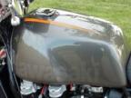
I don't understand why you need to run the fan circuit through the M-Unit. The Kz and ZN 1300's have the fan circuit outside of the ignition on circuit, hence the warning label on the fan shroud to indicate the fan could come on at any time (keep your fingers out)
The 10 A fuse in the original circuit is fed from the White wire with the red tracer directly off of the battery. Coming off of the 10 A fuse is an orange wire with a green tracer which feeds the fan relay and powers the temp switch internally from the fan relay via a red (or orange wire hard to tell from the wiring diagram) wire with a white tracer. No part of the circuit is controlled through either the Main Switch or the Ignition Switch. This is another independent circuit.
I see no purpose in trying to control a circuit that controls itself.
Last edit: 5 years 10 months ago by Kawboy.
Please Log in or Create an account to join the conversation.
Moderators: scotch
Time to create page: 0.657 seconds