Electrical
M-Unit Blue wiring
- McBoney
-
 Topic Author
- Offline
- Platinum Member
-

- Posts: 585
- Thanks: 96
Re: M-Unit Blue wiring
5 years 7 months ago
Well, as the heap of a bike that I bought had NOTHING left of use, or at all (besides the ignition solenoid and the igniter unit), I went the whole hog and effectively I am building from scratch.
M-Unit Blue, M- Button, Motone push buttons (1x 2-button, 1x 3-button), Ultrabatt lithium battery, Mosfet reg/rec, Motogadget wiring kit, Kellerman lights, Acewell speedo and a new key operated ignition switch.
As said I can do the lighting circuit as well as the warning lights for oil, water, neutral etc, but I am unclear on the ignition and charging circuits as I am not sure how they work, in particular when I'm changing the way things run compared to the standard way. The M-unit instructions do not have diagrams for ignition and/or charging systems with Mosfet reg/rec's etc... but there are enough colours and gauges to work with.
I started making an aluminium battery box today, but that was an abject failure as the metal was too thick and I could not bend it properly into shape. I have thinner metal and will have another go tomorrow. I want to get that done and installed first as in my mind that is where it all starts from.
I read about the aux 2 output where you can program in a delay in shutting off... I'll get to that when I have the bike running I think, but definitely on the list!
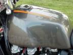
Six-Pot-Cafe in the making...
Please Log in or Create an account to join the conversation.
- Kawboy
-

- Offline
- Sustaining Member
-

- Posts: 3268
- Thanks: 1176
Re: M-Unit Blue wiring
5 years 7 months ago - 5 years 7 months ago
I'll try to keep this brief so as to not get accused of writing another chapter of War and Peace.
The Ignition Circuit on the '79 KZ1300
The White wire with red tracer coming off of the Battery + terminal supplies voltage to the fuse panel @ fuse 30 A and fuse 10 A. We'll concentrate on the 30 A fuse.
Coming off of the 30 A fuse is a White wire with black tracer feeding the Main Switch.
When the Main Switch is closed the White wire on the Main Switch is energized.
The White wire feeds Battery power to the ignition switch.
When the ignition switch is closed, power is fed to the Brown wire.
The Brown wire feeds battery power to the Ignition Kill switch.
When the Kill switch is closed, battery power is fed to the Yellow wire with a red tracer.
The Yellow wire with red tracer feeds battery power to the triple ballast resistors which feeds battery power to the 3 ignition coils.
The Yellow wire with a red tracer also feeds the IC Igniter with battery power.
The ignition system is a transistorized Induction system. There are 3 Darlington transistors (high current transistors) which open and close the ground side of the ignition coils. The pulser coils operate the Darlington transistors. Power to the ignition coils is constantly feed to the ignition coils through the ballast resistors. Only the ground side is operated to create the spark. There is no grounding of the primary circuit to stop the ignition as in a CDI ignition.
The Charging Circuit-
Using the Shindengen SH847 or the FH020aa is simple enough as they both do not need to be turned on or off. They are self contained and operate independently of any and all of the rest of the electrical.
you have 3 yellow wires on the Shindengen that attach to the 3 stator output wires. They take the AC feed from the stator. The Shindengen then rectifies the current to DC and monitors the output of the regulator and maintains the output at charging voltage. The Sh847 does this by opening and closing the output. The Fh020AA does this by shunting the excess voltage to ground through MOSFET transistors. The Black and Red wires from the Shindengen wire directly to the battery through a supplied 30 or 50 A inline fuse as supplied by Roadster Cycle. Simple enough. No need to include any of the charging circuit in your Moto M-Unit circuit.
Last edit: 5 years 7 months ago by Kawboy.
The following user(s) said Thank You: McBoney
Please Log in or Create an account to join the conversation.
- tackelhappy
-

- Offline
- Platinum Member
-

- Posts: 436
- Thanks: 168
Re: M-Unit Blue wiring
5 years 7 months ago - 5 years 7 months ago
From Kawboy "The Black and Red wires from the Shindengen wire directly to the battery through a supplied 30 or 50 A inline fuse as supplied by Roadster Cycle. Simple enough. No need to include any of the charging circuit in your Moto M-Unit circuit. "
That's good. Get the battery mounted in it's box and the m-unit close enough to be able to use the supplied power wire with the 30 amp fuse in between. The m-unit needs to be grounded.
As Kawboy stated , power from the rec/req goes to the battery, no where else. On the original bike , some of the electrical load was supplied from the regulator via a relay. In this system there is one fuse -battery to m-unit- and one relay/ solenoid- the oem starter solenoid- that's it. Everything is powered through the m-unit. ( Except the starter solenoid that is powered directly from the battery but prompted from the m-unit )
" If you can't say what you think, very soon you won't be able to think !
OKANAGAN FALLS. BC ,Canada
OKANAGAN FALLS. BC ,Canada
Last edit: 5 years 7 months ago by tackelhappy.
The following user(s) said Thank You: McBoney
Please Log in or Create an account to join the conversation.
- scotch
-

- Offline
- Sustaining Member
-

- Posts: 2027
- Thanks: 906
Re: M-Unit Blue wiring
5 years 7 months ago
kawboy wrote: <...../ The Shindengen then rectifies the current to AC.....>
?????
you messin' with me, boy? :side:
?????
you messin' with me, boy? :side:
1980 KZ 1300 sr# KZT30A-009997
Always High - Know Fear !
Always High - Know Fear !
The following user(s) said Thank You: Kawboy, McBoney
Please Log in or Create an account to join the conversation.
- Kawboy
-

- Offline
- Sustaining Member
-

- Posts: 3268
- Thanks: 1176
Re: M-Unit Blue wiring
5 years 7 months agoscotch wrote: kawboy wrote: <...../ The Shindengen then rectifies the current to AC.....>
?????
you messin' with me, boy? :side:[/quote
Fixed it. Trying to be brief short circuited my brain.
The following user(s) said Thank You: McBoney
Please Log in or Create an account to join the conversation.
- McBoney
-
 Topic Author
- Offline
- Platinum Member
-

- Posts: 585
- Thanks: 96
Re: M-Unit Blue wiring
5 years 7 months ago
Absolutely awesome gents! Thank you!
I will forge on with the battery box today and have already wired in the reg/rec as per your instructions. I need to still insert a 30Amp fuse though.
I'll report back on progress.
Cheers
Paul
I will forge on with the battery box today and have already wired in the reg/rec as per your instructions. I need to still insert a 30Amp fuse though.
I'll report back on progress.
Cheers
Paul
Six-Pot-Cafe in the making...
Please Log in or Create an account to join the conversation.
Time to create page: 0.176 seconds
