
Electrical
steel box
- dcarver220b
-

- Offline
- Sustaining Member
-

- Posts: 1300
- Thanks: 299

The following user(s) said Thank You: Kawboy
Please Log in or Create an account to join the conversation.
- hoganter
-
 Topic Author
- Offline
- Senior Member
-

- Posts: 43
- Thanks: 7
Re: steel box
3 months 3 weeks ago - 3 months 3 weeks ago
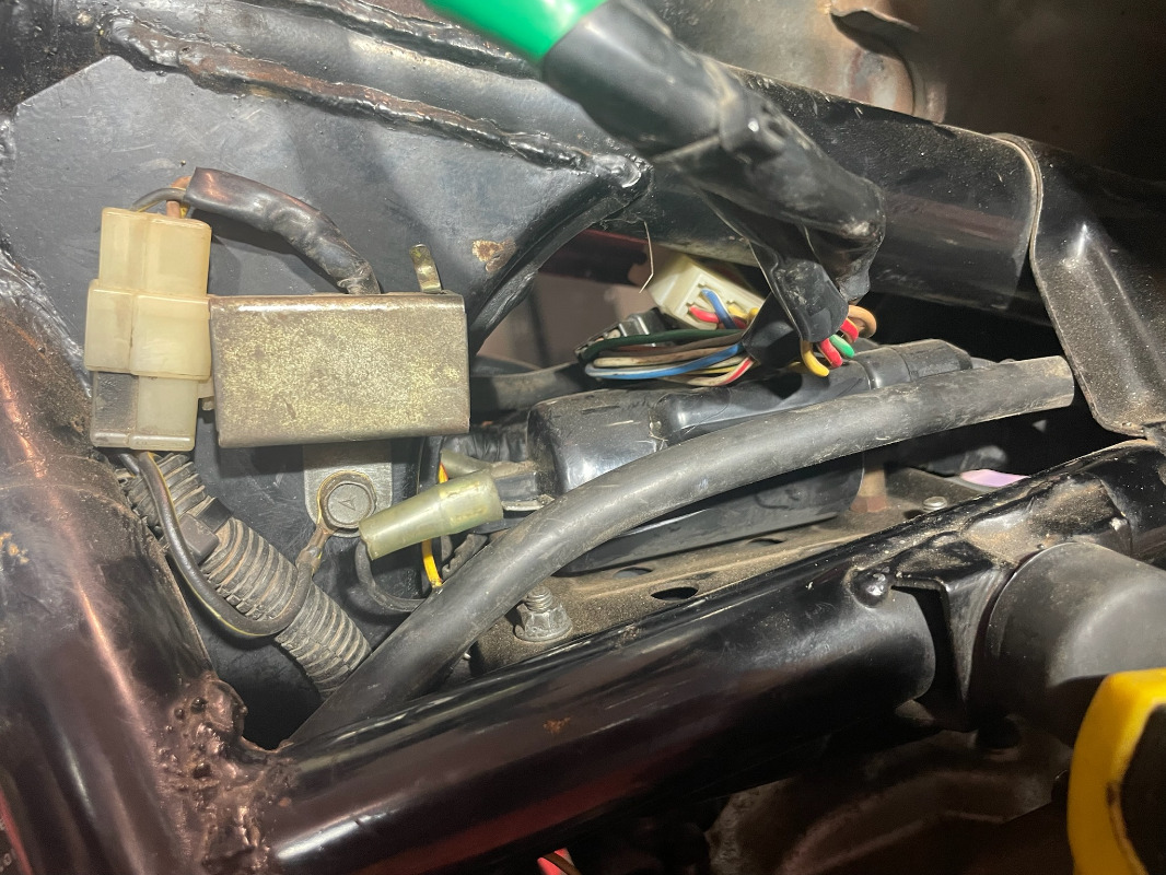
The resistor I have looks different, I don't have the pink wires.
It has 12.87v in and 7.07 out.
Do you reckon I have the correct ignition diagram?
Yes, you have the right diagram. So seldom we get inquiries about the later DFI Voyagers , in your case an 85, which mechanically is very similar to the early KZ1300's but the ignition is radically different. As per your diagram, your coils are fed system voltage ( battery voltage) and your igniter controls the voltage in the system to maintain 12 volts constant in the ignition circuit. That said, you should have batery voltage supplied to the 3 red wires feeding the coil and the red wire feeding the igniter.
There's a note in the service manual which talks about connecting / disconnecting battery voltage when the igntion switch is on and the fact that the igniter could get damaged. It also talks about inadvertently connecting the battery up backwards and damaging the igniter. You mentioned earlier in the topic that this bike suffered a fire and the wiring loom got damaged. Did you sort out through the wiring just what wires were damaged and possibly shorted between the wires? Could it be that the igniter wires were involved? Although, the fact that it runs fine? for 30 minutes then gets stupid seems to indicate that something is acting up when things get heated up. Bit of a head scratcher.
You still need to comfirm the obvious which is battery voltage supplied to the coils and forget the mentioning of a ballast resistor since you don't have one. The "steel box" as we mentioned back at the beginning of the topic reduces the voltage supplied to the fuel tank sensor and the coolant temperature sensor since the fuel gauge and water temp gauge run on a 7 volt circuit.
I don't know if you follow the site on a regular basis. I often mention on electrical topics that the best tool you can make for yourself is to take an electronic copy of the wiring diagram, ( in your case page 37 of the manual) and go to your local print shop and have them blow it up to A2 paper size ( 17" x 24") and print off a color copy. Then have them laminate it (plastic coat) so you can mark it up with a white board marker. When you 're tracing out wiring on your bike, you can mark up the drawing at the same time. When finished your wiring troubleshooting, wipe the diagram clean with paper towel and hang it up as art work in your shop. Best tool I ever made and others on the site have done so as well.
Last edit: 3 months 3 weeks ago by Kawboy.
Please Log in or Create an account to join the conversation.
- hoganter
-
Topic Author
- Offline
- Senior Member
-
- Posts: 43
- Thanks: 7
Last edit: 3 months 3 weeks ago by hoganter. Reason: incorrect format
Please Log in or Create an account to join the conversation.
- hoganter
-
Topic Author
- Offline
- Senior Member
-
- Posts: 43
- Thanks: 7
Re: steel box
3 months 2 weeks ago
Thanks
Correction - I do have battery voltage at the coils ( don't ask)
There was some heat damage, when I got it, in that area which I just rejoined.
Yes I do have the A3 laminates for some of the circuits, good suggestion, wish they were larger.
I printed out the igniter resistance from the other thread, and the readings seem backwards on the large connector and the small connector has different coloured wires.
So not sure.
Will do some reading
The following user(s) said Thank You: Kawboy
Please Log in or Create an account to join the conversation.
- hoganter
-
Topic Author
- Offline
- Senior Member
-
- Posts: 43
- Thanks: 7
Re: steel box
3 months 2 weeks ago
Found this in the notes. ( see attached)
I tested the BK/W wire of the igniter back to the battery and am getting 8.9K Ohms, so looks like its not grounding properly.
Bike wont even start now.
Does anyone know what the 21 is in the box in the diagram and what role the diodes play?
Also I don't reckon I have the "junction box" just a fuse box.
Have included photo of the brains trust ( extra hands ) to hold the multimeter whilst trying to start it.
Please Log in or Create an account to join the conversation.
- Kawboy
-

- Offline
- Sustaining Member
-
- Posts: 3259
- Thanks: 1206
Re: steel box
3 months 2 weeks agoFound this in the notes. ( see attached)
I tested the BK/W wire of the igniter back to the battery and am getting 8.9K Ohms, so looks like its not grounding properly.
Bike wont even start now.
Does anyone know what the 21 is in the box in the diagram and what role the diodes play?
"21" is the pin # on the connection.
The diodes are one way check valves allowing the current to flow in the direction of the arrow in the diagram
Also I don't reckon I have the "junction box" just a fuse box.
Have included photo of the brains trust ( extra hands ) to hold the multimeter whilst trying to start it.
These side stand switches have caused a lot of trouble over the years probably because they are located very exposed to the elements . I'd test the side stand switch with the ohm meter attached and operate the side stand and see if it open circuits intermittently.
Please Log in or Create an account to join the conversation.
Moderators: scotch
Time to create page: 0.171 seconds