I could create an entire new topic on the camshafts but this is my journey through the rebuild conversion of my bike, so I carry on.
As I suggested, I will tool up my baby Altas Coulson lathe and make a camshaft profile grinder and grind my own camshafts. to do this I will have to make up a master for the profile grinder to follow. Quite often, if a machine shop doesn't have a master for the grind you want them to put on your camshafts, they will have to custom make a profile for your job. Anyone in the business can do this and you pay them to make the profile (usually $200) and they get to keep the profile. Usually they will copy a camshaft that's close to your spec, and then tweak the profile by hand. Or if there's a cam out there with your spec and you can get your hands on it, they can profile off of it. In my case right now, I'm out of luck. There is a camshaft for a VW GTI with 270 duration and .350" lift, but I haven't got one and I'm not about to buy one either. So, I decided to set up one of my 6 intake camshafts and map it out to see if I could use it to make the profile.
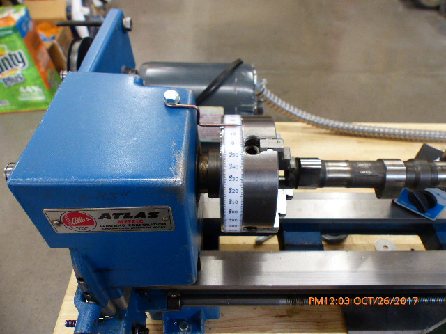
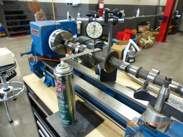
So here's my baby lathe with the cam chucked up and a mag. base dial indicator set up. The aerosol can and the 6" scale are set up to replicate the shim bucket because, as the cam rotates around the contact area on the cam actually swipes across the face of the shim bucket so you can't just indicate to the cam. The readings will be wrong. You'll be able to see what I'm talking about in one of the later pictures.
I needed to be able to degree the camshaft as I took readings, so I went to a website (
www.blocklayer.com/timing-tape.aspx ) and created a timing tape to fit my 100mm chuck. I also drilled a hole and tapped for a 6mm X 1mm bolt in the headstock of the lathe and then fabricated up an indicator needle that works with the timing tape.
The camshaft was setup at timing top dead center with the timing tape at 0 degrees and I started mapping out the lobe on #4 cylinder. What i discovered was that the lift on the lobe reached .005" at top dead center #4 when it should be 20 degrees before top dead center and finished 170 camshaft degrees later which is equivilant to 340 degrees of duration instead of 270 degrees of duration. WTF !!! Believe me, I checked everything 3 or 4 times. If I had installed this cam and set the shims at .005" the intake would open 20 degrees late and close 70 degrees late. REALLY ?? How can one explain this phenomenon?
1. Maybe a shitty grind right from the factory? It's possible.
2. As the camshafts wear, material will be removed from the wearing surfaces and that could lengthen the effective area of the cam profile but if you look at the pictures coming, you'll see that the majority of the work done by the cam to open and close the valves is done by the toe of the cam. The service height of this cam only shows .006" of wear off of the toe.
The flanks of the cam are so close to being flat that the first 20 degrees of cam rotation (which is 40 degrees of crankshaft rotation) only produce .010" lift. So in this case, at 40 degrees after top dead center when the piston will be reaching maximum velocity, the intake valve will be barely off of its seat. Talk about sucking a dead head!!
Let's chart this up so you can see what's going on. All these number are in crankshaft degrees after TDC.
0 deg. .005"
10 deg .007"
20 deg ..010"
30 deg .012"
40 deg .015" The cam is lazy up to this point . it only lifted .003" in the last 10 degrees This is the point where the piston is reaching maximum velocity
50 deg .034" Now we're starting to move Lifted .015" in the last 10 degrees.
60 deg .066" .032" in the last 10 degrees
70 deg .102" .036" last 10 degrees
80 deg .137" .035" last 10 degrees
90 deg.170" .033" last 10 degrees
100 deg .200" .030" last 10 degrees
110 deg .229" .029" last 10 degrees
120 deg .255" .026" last 10 degrees (you can see the deceleration coming on )
130 deg .278" .023" last 10 degree
140 deg .299" .021" last 10 degrees
150 deg .314" .015" last 10 degrees
160 deg .324" .010" last 10 degrees
170 deg .330" .006" last 10 degrees
180 deg .330" .000" last 10 degrees
190 deg .326" -.004" last 10 degrees
200 deg 316" -.010" last 10 degrees
210 deg .300" -.016" last 10 degrees
220 deg .280" -.020" last 10 degrees
230 deg .252" -.028" last 10 degrees
240 deg 223" -.029" last 10 degrees
250deg .187" -.036" last 10 degrees valve is picking up speed closing but we are now 30 degrees after bottom dead center
260 deg .151" -.036" last 10 degrees Piston is now approaching maximum velocity and the valve is open .151" Intake valve is supposed to be closed at this point.
270 deg .110" -.041" last 10 degrees
280 deg .066" -.056: last 10 degrees Point of maximum deceleration of the cam follower.
290 deg .030" -.036" last 10 degrees Deceleration starting to slow down
300 deg .015" -.015" last 10 degrees More rapid deceleration. This should have happened a long time ago
310 deg .011" -.004" last 10 degrees Cam is virtually flat at this point but the valve is still open
320 deg ..009" -.002" last 10 degrees Valve is still open .004" off of the seat
330 deg ..007" -.002" last 10 degrees Valve is still open .002" off of the seat
340 deg .005" -.002" last 10 degrees Valve is finally fully closed.
bottom line - this camshaft is dead. It would be possible for this cam to jump a tooth on the cam chain and still not bend any valves. The intake is late 20 degrees on opening which means no effective valve overlap so the intake gases haven't started to be drawn in from scavenging.
The late closing would cause the compression to be very low since the piston has no dwell to build pressure.
The opening ramp doesn't start to get going until 50 degrees into the opening of the valve and then rapid acceleration as the toe of the lobe starts to engage the cam follower. At that point the cam is throwing the valve open. If the ramp was more progressive at the beginning of the opening and developed more constantly, then the velocity of the valve would be more constant and more of the flank would be doing the work rather than the toe of the cam. This would also progress the valve such that more volume efficiency would happen. 270 degree duration cam is a very aggressive cam. This engine should flow tonnes. Dead cams like this and late on opening and closing - thing would run like a piece of shit.
One thing I did see was the punch mark on the cam for lining up when installing was punched sort of down in the bottom of 2 gear teeth instead of under the tip of the tooth. I assumed that it was of slightly and the tip of the tooth closest to the punch mark was chosen for reference to top dead center. If I used the tip that appeared to be behind the punch mark then the opening of the valve would have been spot on for opening at 20 degrees before top dead center and the closing would have been at 320 degrees but even 320 degrees would have been 50 crank degrees late.
This is the kind of work engine blue printers do and you can see why. This cam needs a lot of work. What this mapping shows is the effect of the valve timing on a worn camshaft.
The next question will be if I can save it and if it can be possible to speed up the opening on a more constant acceleration and then a more constant deceleration. This is the kind of work Hideo Yoshimura started back in the 1970's. If you're truly interested in this topic of camshafts then have a read through the stories at
www.bikebros.co.jp/vb/sports/sfeat/yoshimura-cam-en/ Motor heads love this stuff. (That would be me!! )
Hopefully you can see why I had to use the 6" scale to mimic the cam follower. This is not easy to see when the cam is in the head but you can see how the cam lobe is wiping across the scale like the head of a wooden match when you try to strike it.

")