
Head on Valve Spring Compressor 1/4
- scotch
-
 Topic Author
- Offline
- Sustaining Member
-

- Posts: 1970
- Thanks: 875
Head on Valve Spring Compressor 1/4
7 years 6 months ago - 7 years 6 months ago
Just changed my Valve stem seals. Came up with this because I was NOT removing the cyl-head.
It works perfectly!
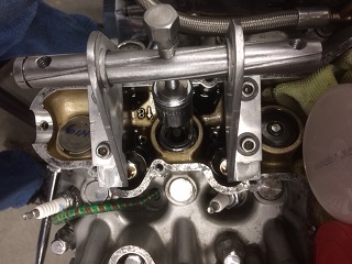
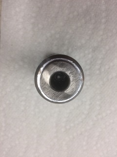
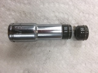
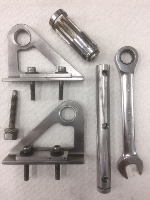
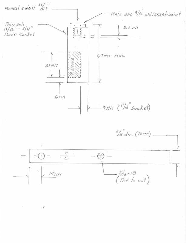
The two brackets were made from a scrap piece of 5/23” (4mm?) angle-steel. The 5/8” rod” is readily available. I had a length of similar from another piece of equipment so used it. The “working” end is an 11/16” deep socket. I cut the top and bottom laterally with a band-saw and simply ground-out everything in-between on my bench grinder and cleaned it up with some files. The “adapter” in the top of the socket was cannibalized from a 3/8” universal joint. After separating the joint parts I annealed the male piece so I could cut-off the "ears” and drill into (NOT THROUGH) the end. When drilled-out the spring-loaded locking-ball is lost so I used some brass shim-stock over the Male-end to create a tight fit and pressed the two pieces together. The socket and “adapter” could also be welded.
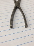
The compression-bolt is from a pair of “Vice-Grip” brand vice-grips. The thread is 5/16”-18. If you use an “off-shore” brand then the “rod” will need to be tapped to the corresponding Metric thread. This bolt was used because it has the unthreaded tip and just happened to be the perfect length.. This is very important! More about this later. A 14mm nut was welded to the knurled end of the bolt. This allows a 14mm ratchetting wrench to be used to tighten and loosen the bolt and used for rotating the engine via the Alternator rotor. The knurled end by luck was larger than the 14mm nut so it stops the wrench from slipping down.
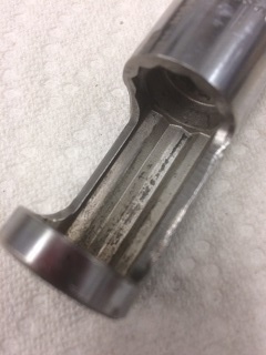
I had intended on using a larger diameter “Rod” and drilled the brackets for that size but decided for “design” reasons to reduce the rod diameter. Hence the aluminum reduction “sleeves” seen in the photos. The rod is drilled and tapped on each end and the middle to accept the bolt. In reality it only needs to be tapped in the center and on 1 end. The length of the bolt (from the vice-grips) was somewhat critical to the overall design – which is where the “tweaking” was required as mentioned earlier. The unthreaded tip of this bolt fits deeper into the drilled end of the “adapter” (the former universal joint male end). This prevents the rod from rotating in either direction when under tension and spitting out the socket and potentially the keepers.

It works perfectly!
The two brackets were made from a scrap piece of 5/23” (4mm?) angle-steel. The 5/8” rod” is readily available. I had a length of similar from another piece of equipment so used it. The “working” end is an 11/16” deep socket. I cut the top and bottom laterally with a band-saw and simply ground-out everything in-between on my bench grinder and cleaned it up with some files. The “adapter” in the top of the socket was cannibalized from a 3/8” universal joint. After separating the joint parts I annealed the male piece so I could cut-off the "ears” and drill into (NOT THROUGH) the end. When drilled-out the spring-loaded locking-ball is lost so I used some brass shim-stock over the Male-end to create a tight fit and pressed the two pieces together. The socket and “adapter” could also be welded.
The compression-bolt is from a pair of “Vice-Grip” brand vice-grips. The thread is 5/16”-18. If you use an “off-shore” brand then the “rod” will need to be tapped to the corresponding Metric thread. This bolt was used because it has the unthreaded tip and just happened to be the perfect length.. This is very important! More about this later. A 14mm nut was welded to the knurled end of the bolt. This allows a 14mm ratchetting wrench to be used to tighten and loosen the bolt and used for rotating the engine via the Alternator rotor. The knurled end by luck was larger than the 14mm nut so it stops the wrench from slipping down.
I had intended on using a larger diameter “Rod” and drilled the brackets for that size but decided for “design” reasons to reduce the rod diameter. Hence the aluminum reduction “sleeves” seen in the photos. The rod is drilled and tapped on each end and the middle to accept the bolt. In reality it only needs to be tapped in the center and on 1 end. The length of the bolt (from the vice-grips) was somewhat critical to the overall design – which is where the “tweaking” was required as mentioned earlier. The unthreaded tip of this bolt fits deeper into the drilled end of the “adapter” (the former universal joint male end). This prevents the rod from rotating in either direction when under tension and spitting out the socket and potentially the keepers.
1980 KZ 1300 sr# KZT30A-009997
Always High - Know Fear !
Always High - Know Fear !
Last edit: 7 years 6 months ago by scotch.
The following user(s) said Thank You: biltonjim, zed_thirteen
Please Log in or Create an account to join the conversation.
- scotch
-
Topic Author
- Offline
- Sustaining Member
-
- Posts: 1970
- Thanks: 875
Re: Head on Valve Spring Compressor 2/4
7 years 6 months ago - 7 years 6 months ago
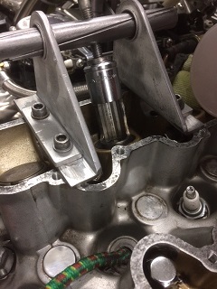
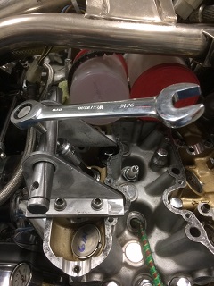
The two aluminum “spacers” on the brackets flanges were required to account for the cam-cap guides being taller than the thickness of the bracket material. 35mm M6X1.0P socket heads hold the brackets to the cam bearing towers. They need merely to be snugged. A ball-end “L” Allan key works perfectly with no frame obstructions when using. To avoid any chance of damaging the cyl-head cam-cap surface I trued the bottom surface of the flanges on a sheet of emery on a flat surface.
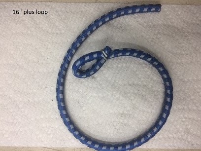
I used a 16” length of Bungee cord Inserted into the plug-hole when the piston was ½ way to TDC. Then finished rotating the crank until the piston stopped against the cord.
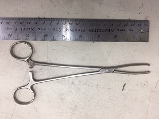
The brackets need to be installed with the flanges facing each other. In most cases the “keepers” popped on the first try. The valve being compressed will rotate the crank backwards somewhat. The ratcheting wrench is used to return the piston to its highest point. In several cases simply bringing the piston back towards TDC (until it stopped) made the keepers pop. Two cylinders had keepers that would not release. A “slight” tap with a brass drift to the top of the keeper retainer, released them. I used a small magnet to remove the keepers. I used the same magnet to remove the shim bucket and valve springs. I cleaned the buckets and numbered them to their respective cyl and valve! The shims stayed in the buckets. I used a pair of forceps (dentist?) to remove the old seals. It took several attempts per seal but worked well. Given the length of them I found it easier to remove the inside rod-bracket for the seals on Exhaust and Intake # 3 and “4.
I used a 16” length of Bungee cord Inserted into the plug-hole when the piston was ½ way to TDC. Then finished rotating the crank until the piston stopped against the cord.
The brackets need to be installed with the flanges facing each other. In most cases the “keepers” popped on the first try. The valve being compressed will rotate the crank backwards somewhat. The ratcheting wrench is used to return the piston to its highest point. In several cases simply bringing the piston back towards TDC (until it stopped) made the keepers pop. Two cylinders had keepers that would not release. A “slight” tap with a brass drift to the top of the keeper retainer, released them. I used a small magnet to remove the keepers. I used the same magnet to remove the shim bucket and valve springs. I cleaned the buckets and numbered them to their respective cyl and valve! The shims stayed in the buckets. I used a pair of forceps (dentist?) to remove the old seals. It took several attempts per seal but worked well. Given the length of them I found it easier to remove the inside rod-bracket for the seals on Exhaust and Intake # 3 and “4.
1980 KZ 1300 sr# KZT30A-009997
Always High - Know Fear !
Always High - Know Fear !
Last edit: 7 years 6 months ago by scotch.
The following user(s) said Thank You: zed_thirteen, DannyKZ
Please Log in or Create an account to join the conversation.
- scotch
-
Topic Author
- Offline
- Sustaining Member
-
- Posts: 1970
- Thanks: 875
Re: Head on Valve Spring Compressor 3/4
7 years 6 months ago - 7 years 6 months ago
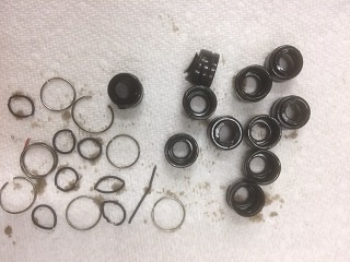
The seal has a lower wire circular clip to hold it on the valve-guide tower and a very fine tensioning spring for the valve-stem seal lip. Both came off in the process of removing the old seal. I wiped out the oil from the bucket-well to ensure there was no spring or clip or part there-of, hiding in the oil.. All accounted for.
Oiled the new seals and used a 3/8 drive 3/8” deep socket to push the seal home. Reassembly of the springs, keepers and buckets is simply in the reverse of the removal.
A small drop of grease on the inside of each cleaned keeper lets them stick to the valve stem. A small magnetized screwdriver was used to insert and position them. For some I could drop them in place with my fingers. If the grease was being squeezed out as the spring was being released then they were going into position.
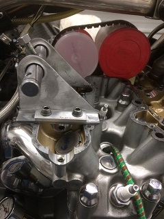
I later chose to remove the center material of the brackets. Even in a brightly lit shop I relied on a small flashlight a lot. Being able to shine the light through that opening was handy.
To give you an idea of how worn my valve seals were: Using some standard drills I found the two that would give the same “feel of fit” in a new seal and an old.
New seals – 6.26mm dia.
Old seals – 7.63mm dia.
Oversize +1.3 mm. After 80,000 kilometers I guess they were due!
The 4 cam-cover rubbers (Original) had started to weep this year, just enough to have dust stick. They're fairly "firm" as you'd expect. For now I tried this: I put 1 wrap of Yellow (Heavy Duty Gas fitters) Teflon tape around them. I used an "Exacto"-blade to cross cut for the holes. I'll see if this keeps them dry. The cam-cover gasket had to be replaced in '83 when I stripped the bike for painting and plating. The original was stuck in too many spots to save. So the one I'm using is 34 yrs old and still keeping the top-end dry. When I originally installed it I put a thin film of oil on the HEAD-side. To this day it comes off the head cleanly, staying stuck to the cover. There are areas where there has been some slight gasket material transfer to the head - barely enough to feel. I've never tried to remove this ! As I said - It still keeps the top end dry. I ALWAYS torque the cover bolts but NEVER to the 11ft/lbs. the manual recommends. I use an inch/lbs. "click-type" torque-wrench torquing in two stages - 1st to about 30 inch lbs and then to 55 inch/lbs. The manual states 11 ft lbs (132 inch lbs - www.kylesconverter.com ) which (in my opinion) is either a misprint or simply getting too close to stripping the threads - at this age. (The bikes - not mine !)
My next goal is to see if I can fit a threaded O-ringed flat cap in the center of the stator cover so the 14mm rotor-bolt can be accessed to turn the crank-shaft without the need to drain the oil or have the bike inconveniently leaning on the side stand.
Oiled the new seals and used a 3/8 drive 3/8” deep socket to push the seal home. Reassembly of the springs, keepers and buckets is simply in the reverse of the removal.
A small drop of grease on the inside of each cleaned keeper lets them stick to the valve stem. A small magnetized screwdriver was used to insert and position them. For some I could drop them in place with my fingers. If the grease was being squeezed out as the spring was being released then they were going into position.
I later chose to remove the center material of the brackets. Even in a brightly lit shop I relied on a small flashlight a lot. Being able to shine the light through that opening was handy.
To give you an idea of how worn my valve seals were: Using some standard drills I found the two that would give the same “feel of fit” in a new seal and an old.
New seals – 6.26mm dia.
Old seals – 7.63mm dia.
Oversize +1.3 mm. After 80,000 kilometers I guess they were due!
The 4 cam-cover rubbers (Original) had started to weep this year, just enough to have dust stick. They're fairly "firm" as you'd expect. For now I tried this: I put 1 wrap of Yellow (Heavy Duty Gas fitters) Teflon tape around them. I used an "Exacto"-blade to cross cut for the holes. I'll see if this keeps them dry. The cam-cover gasket had to be replaced in '83 when I stripped the bike for painting and plating. The original was stuck in too many spots to save. So the one I'm using is 34 yrs old and still keeping the top-end dry. When I originally installed it I put a thin film of oil on the HEAD-side. To this day it comes off the head cleanly, staying stuck to the cover. There are areas where there has been some slight gasket material transfer to the head - barely enough to feel. I've never tried to remove this ! As I said - It still keeps the top end dry. I ALWAYS torque the cover bolts but NEVER to the 11ft/lbs. the manual recommends. I use an inch/lbs. "click-type" torque-wrench torquing in two stages - 1st to about 30 inch lbs and then to 55 inch/lbs. The manual states 11 ft lbs (132 inch lbs - www.kylesconverter.com ) which (in my opinion) is either a misprint or simply getting too close to stripping the threads - at this age. (The bikes - not mine !)
My next goal is to see if I can fit a threaded O-ringed flat cap in the center of the stator cover so the 14mm rotor-bolt can be accessed to turn the crank-shaft without the need to drain the oil or have the bike inconveniently leaning on the side stand.
1980 KZ 1300 sr# KZT30A-009997
Always High - Know Fear !
Always High - Know Fear !
Last edit: 7 years 6 months ago by scotch.
The following user(s) said Thank You: zed_thirteen, DannyKZ, Ledkz1300
Please Log in or Create an account to join the conversation.
- Kawboy
-

- Offline
- Sustaining Member
-
- Posts: 3193
- Thanks: 1134
Re: Head on Valve Spring Compressor 3/4
7 years 6 months ago - 7 years 6 months ago
Nicely done Scotch. Simple to use and all the work when compressing the spring pack and dealing with the keeps can be done in a controlled manner. Love it !! There's a lot of different styles of compressors which are generic and because of that, there's always a possibility of damaging the bores in the head that the shim buckets ride in. Your design looks like once it's set up for one valve, there's little chance of the tool moving around and messing up the bore in the head. Great job. !!
Patent pending I'll assume.
Patent pending I'll assume.
Last edit: 7 years 6 months ago by Kawboy.
The following user(s) said Thank You: scotch
Please Log in or Create an account to join the conversation.
- scotch
-
Topic Author
- Offline
- Sustaining Member
-
- Posts: 1970
- Thanks: 875
Re: Build your own Head on Valve Spring Compressor 4/4
7 years 6 months ago - 7 years 6 months ago
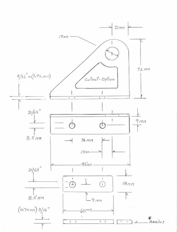
Measure accurately, center-punch deep, drill 1/8" pilot holes first. There's some simply geometry involved. Changing the relationship of the mounting holes (2 per) and the upper rod-hole (1 per), relative to their spacing and height will create alignment problems.
1980 KZ 1300 sr# KZT30A-009997
Always High - Know Fear !
Always High - Know Fear !
Last edit: 7 years 6 months ago by Kawboy.
Please Log in or Create an account to join the conversation.
- Bucko
-
- Offline
- Platinum Member
-

- Posts: 701
- Thanks: 174
Re: Head on Valve Spring Compressor 1/4
7 years 6 months ago - 7 years 6 months ago
You can do the job with a plunger style valve keeper installation/removal tool and some rope. With the motor out of the frame, it takes me less than an hour to do all the seals on my 16 valve Honda. Apparently the tool can be cut (shortened) allowing it to be used with the motor in the frame but I've never tried it (but I'm going to ") ).
).

).
Hello from Canada's We(s)t coast.
Last edit: 7 years 6 months ago by Bucko.
Please Log in or Create an account to join the conversation.
Time to create page: 0.234 seconds